This is a simple experiment by which one can view diode VI characteristics on a scope using the XY feature.
Setup
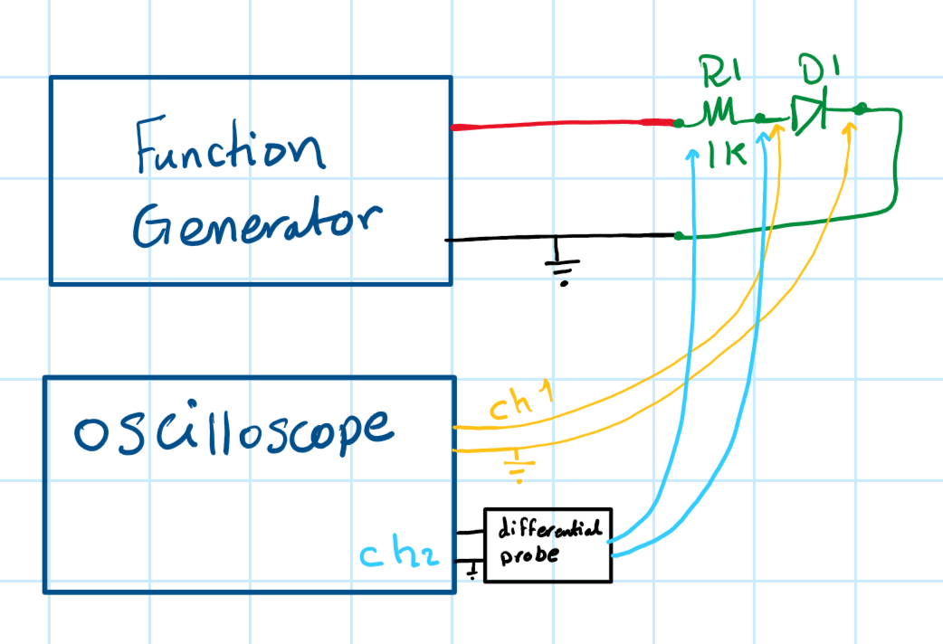
- A function generator is used to generate a low frequency (around 2Hz) triangular signal with a peak-to-peak voltage of around -4V to +4V.
- The resistor-diode network is placed between the function generator positive and negative (Earth) terminal, R1 = 1kOhms.
- An oscilloscope with at least two channels is used to measure two voltage measurements:
- Oscilloscope channel one measures the voltage across the diode (VAK); this is the X-axis in the VI characteristics.
- Oscilloscope channel two measures the voltage across the 1k resistor, this is the Y-axis in VI characteristics, there is a small trick here, an isolated differential probe has to be used to avoid an unintentional Earth loop.
- The only remaining thing is to turn on XY mode in the scope and tune x and y scales to provide a clear view.
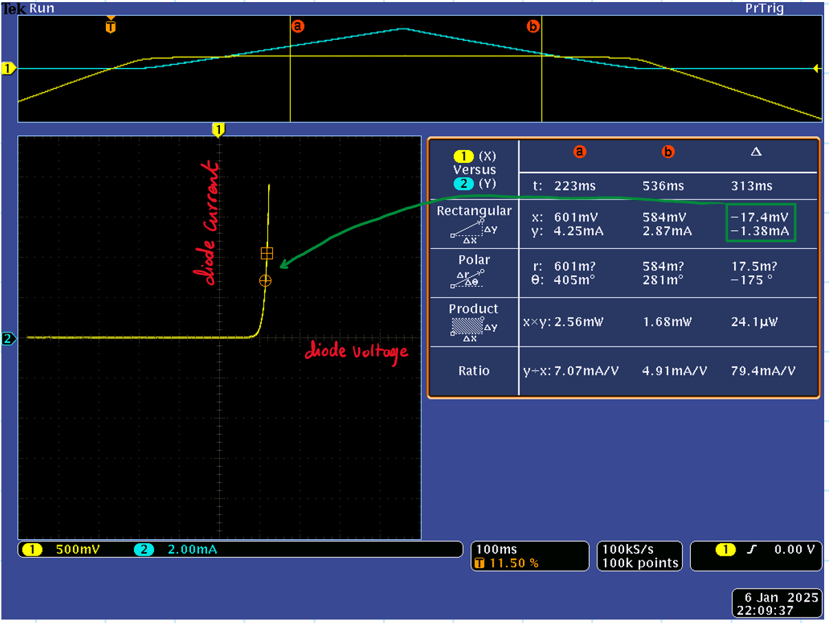
Measurements
The result shows a typical diode performance, the diode starts conducting at around 500mV, and after this point, the curve shows a small dynamic resistance.

Repeating the same experiment but with a zener diode instead, shows the expected zener VI curve. The zener I’m using has a 10V zener breakdown.


Leave a comment